
 EN
EN
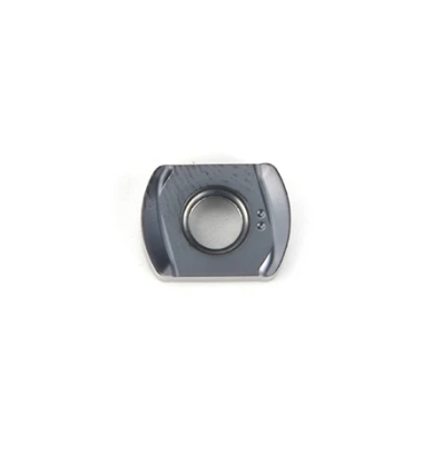
Selecting the correct nose radius for turning inserts is one of the most critical decisions in precision machining. The nose radius directly influences surface finish quality, cutting forces, tool life, and overall machining efficiency. Many machinists struggle with this choice because nose radius specifications appear on every technical drawing, yet the relationship between radius size and actual cutting performance remains misunderstood. This article explains the practical principles behind nose radius selection for turning inserts, helping you make informed decisions that reduce scrap, extend tool life, and improve part quality.
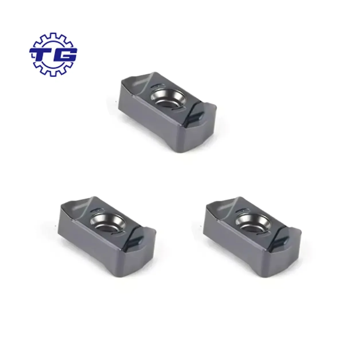
The nose radius of turning inserts acts as the primary contact point between tool and workpiece. A larger nose radius delivers superior surface finish and better heat distribution, while a smaller radius reduces cutting forces and improves chip control in difficult materials. Understanding this tradeoff is essential because the wrong choice for your specific application can result in poor surface finishes, premature tool wear, broken inserts, or extended cycle times. Whether you work with stainless steel, cast iron, or aluminum, the principles of nose radius selection for turning inserts remain consistent, though the optimal range shifts based on material properties and machine rigidity.
Understanding Nose Radius Fundamentals for Turning Inserts
What the Nose Radius Measures on Turning Inserts
The nose radius of turning inserts refers to the rounded corner at the tool tip where the flank and rake faces meet. This radius is measured in millimeters or fractions of an inch and typically ranges from 0.4 mm to 1.6 mm in general machining applications. Turning inserts with larger nose radius values create a wider contact area with the workpiece, distributing cutting loads across a greater surface. This geometry is fundamentally different from sharp or honed edges, which concentrate forces into a smaller zone. The nose radius directly affects how turning inserts perform under varying conditions, making it a primary specification on tool catalogs and insert selection charts.
How Nose Radius Geometry Impacts Cutting Performance
The nose radius geometry on turning inserts influences several critical aspects of cutting performance. A larger nose radius on turning inserts increases the effective cutting edge length, which strengthens the tool and reduces the intensity of cutting forces at any single point. This extended edge geometry allows turning inserts to handle interrupted cuts and varying material hardness more reliably. Conversely, a smaller nose radius concentrates cutting energy into a tighter area, producing lower overall cutting forces but creating higher edge pressures. For turning inserts operating in low-rigidity machines or on flexible workpieces, this concentrated force can cause chatter, vibration, and premature failure. Understanding this geometry relationship helps you predict how turning inserts will perform before tool changeover.
Matching Nose Radius to Material and Finish Requirements
Surface Finish Demands and Nose Radius Selection
Surface finish quality is often the primary driver when selecting nose radius for turning inserts. The nose radius directly determines the theoretical surface finish because the rounded geometry creates a predictable wave pattern on the workpiece surface. Larger nose radius values on turning inserts produce finer surface finishes when feed rates are optimized correctly. For precision applications requiring Ra values below 0.8 micrometers, turning inserts with nose radius between 0.8 mm and 1.2 mm are typically specified. Smaller nose radius values sacrifice finish quality but enable faster feeds on materials prone to work hardening, such as stainless steel. When the drawing calls for specific surface finish targets, the nose radius of your turning inserts must be large enough to achieve those targets without running prohibitively slow feeds.
Material Type Influence on Nose Radius Choice
Different materials demand different nose radius strategies for turning inserts. Ductile materials like aluminum and soft stainless steel benefit from larger nose radius on turning inserts because the geometry helps break and control chips while producing excellent surface finish. Hard materials like cast iron and tool steel often perform better with slightly smaller nose radius on turning inserts because the concentrated force helps fracture brittle material, reducing adhesive wear and built-up edge formation. Turning inserts operating on material with varying hardness, such as forged steel with scale, require careful nose radius selection because the tool must handle both soft and hard zones without chatter. Material composition, hardness range, and surface condition all influence whether you should select turning inserts with aggressive or conservative nose radius geometry.
Optimizing Nose Radius for Tool Life and Productivity
Balancing Cutting Forces and Tool Wear Mechanisms
The nose radius of turning inserts directly affects the types and severity of wear patterns that develop during cutting. A larger nose radius on turning inserts distributes heat and wear more evenly across the cutting edge, extending tool life in many conventional applications. However, excessive nose radius on turning inserts can increase cutting forces beyond what your machine spindle can deliver efficiently, causing rubbing and accelerated flank wear. The ideal nose radius for turning inserts represents the largest geometry that your machine, workholding, and material combination can support without exceeding power limits or generating excessive vibration. Turning inserts with properly sized nose radius will show gradual, predictable wear patterns rather than sudden failure or chatter marks.
Achieving Maximum Productivity Within Machine Constraints
Maximizing productivity with turning inserts requires matching nose radius to your specific machine's rigidity, power, and spindle capability. Rigid machines with high power ratings can effectively handle turning inserts with larger nose radius, enabling higher feeds and deeper cuts while maintaining excellent surface finish. Older machines or spindles with lower power often perform better with turning inserts featuring smaller nose radius because the reduced cutting forces fit within available power budgets. The nose radius of your turning inserts should represent the largest practical size that keeps spindle power consumption below 80 percent of rated capacity. When you select turning inserts with oversized nose radius for your machine constraints, you sacrifice productivity through reduced feed rates and potential tool breakage. Conversely, undersized nose radius on turning inserts wastes your machine's capacity and increases part cost through extended cycle times.
FAQ
How do I determine the correct nose radius for my turning inserts if no specification is given?
If your drawing does not specify surface finish or nose radius, start by assessing your application's dominant priority: finish quality, tool life, or productivity. For general-purpose turning inserts, a nose radius between 0.8 mm and 1.2 mm represents a reliable middle ground for most steel and stainless applications. Test turning inserts with this range, observe the surface finish and tool life, then adjust either larger or smaller based on results. Always consider your machine's rigidity and available spindle power when selecting nose radius for turning inserts, as these factors often constrain what geometry will actually work in your shop.
Can a smaller nose radius on turning inserts improve surface finish?
No, a smaller nose radius on turning inserts typically produces coarser surface finish because the theoretical peak-to-valley pattern created by the nose geometry is smaller. However, if your workpiece exhibits vibration or chatter, reducing nose radius on turning inserts may actually improve the finish appearance by reducing harmonic marks. In this scenario, the finish improves not because of the smaller radius itself, but because chatter is eliminated. The real solution is to address machine rigidity, then return to an appropriately sized nose radius for turning inserts that matches your material and finish requirements.
What happens if I use turning inserts with too large a nose radius for my machine?
Turning inserts with excessive nose radius will generate cutting forces that exceed your machine's power capacity, resulting in spindle stalling, reduced feed rates, or tool breakage. The larger nose radius on turning inserts concentrates more material in the cutting zone, requiring proportionally more energy to remove each chip. Your machine will compensate by slowing the feed, increasing cycle time, and reducing the productivity gains you expected. In severe cases, oversized nose radius on turning inserts can cause chatter if the machine lacks sufficient rigidity, leading to poor surface finish and rapid flank wear despite the theoretically superior geometry.